
 |
||
|
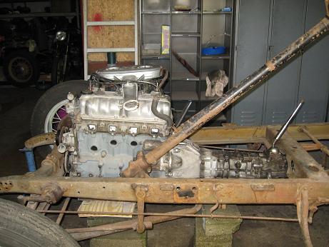
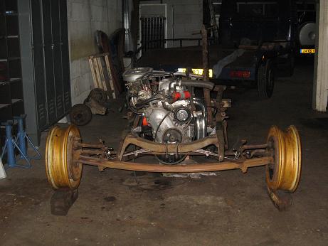
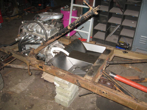
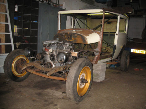
This the first fitting of the new baby-Hemi 4 banger in the A chassis. It became clear that the front and second crossmember would have to loose some weight to make this setup fit... |
|
|
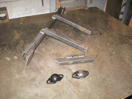
First steps into making small boxing plates and motor mounts. The rubber part is originally from a Peugeot 205. |
|
|
|
A mock up of the motor mount, incl. the part that is going to be attached to the engine side. |
|
|
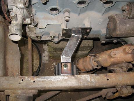
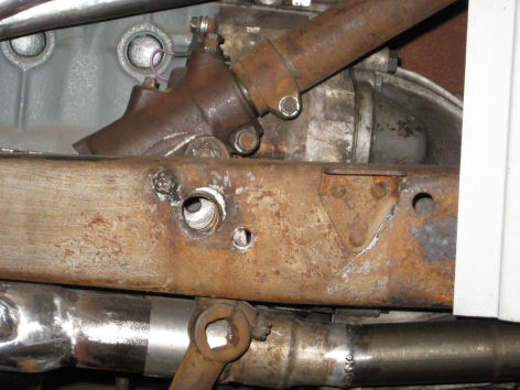
The complete new motor mount, mounted on the engine and welded in the chassis (driver side). |
|
|
|
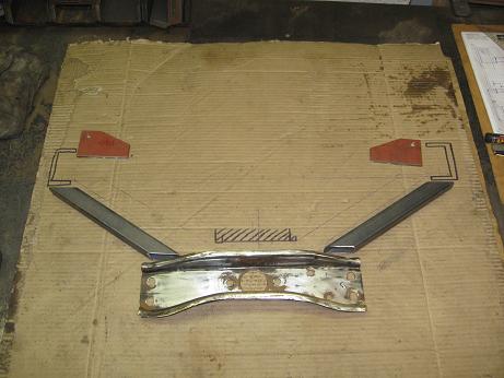
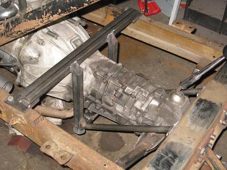
With the engine mounts sorted, it was time to design a new transmission mount, which will incorporate (parts of) the original mount that came with the tranny. |
|
|
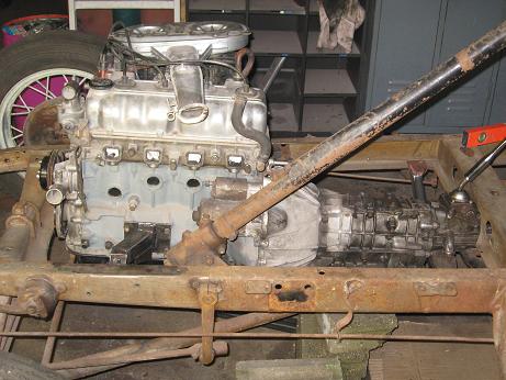
The new engine and transmission firmly mounted in the A Ford chassis. |
|
|
|
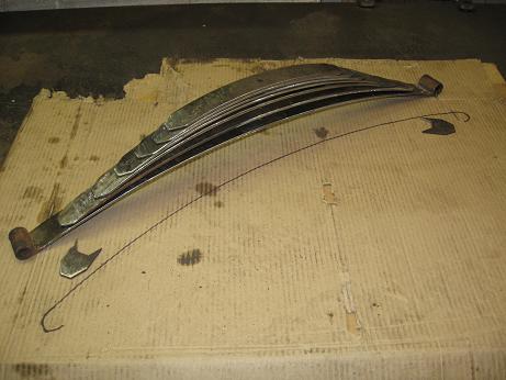
In order to lower the car, I reversed the eyes on the main leaf, and smoothed and chamfered all the other leaves. In the final assembly the complete spring lost 3 of it's 10 leafs. :-) |
|
|
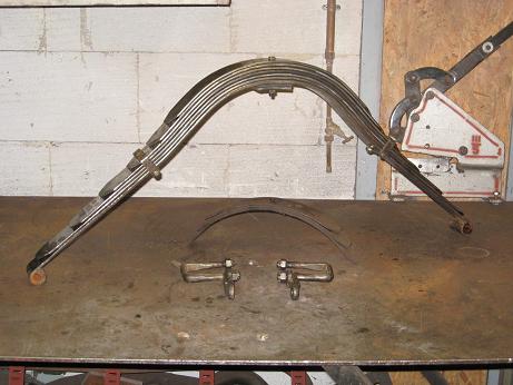
The rear spring also received some TLC; it got smoothed and chamfered, and lost 3 of it's leaves. |
|
|
|
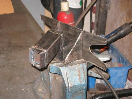
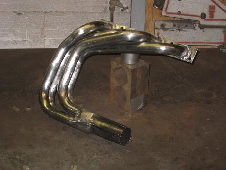
To make my new engine breath properly, I fabricated these headers. Whwn installed on the engine in the chassis, it looked like this. |
|
|
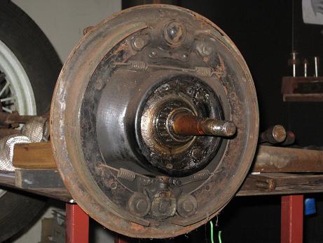
Since I would use a rear axle from a more modern Ford ('71 17M), the front mechanical brakes had to be upgraded to Hydraulics. Because I could not find a proper complete set of early Ford juice brakes, I decided to figure out how to convert the current brakes to hydraulics. With the use of a modern Audi/Volkswagen rear brake cylinder I managed to get them to work. Time will tell if the small bore cylinder is up to the task, or that I have to upgrade to a bigger cylinder (which unfortunately will result in serious surgery of the backing plates...) |
 |
|
|
Front axle fitted to the car, incl. the '34 Renault rims. |
|
|
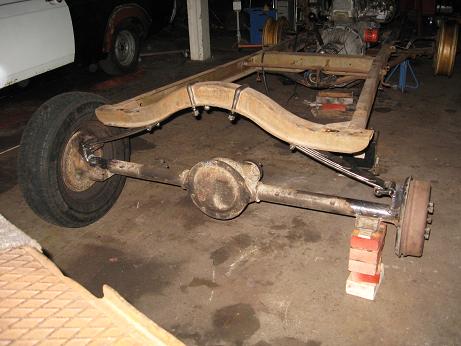
The rear axle got converted from 2 parallel leaf springs to the Model A buggy spring set up. Before and After. |
|
|
|
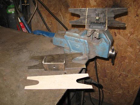
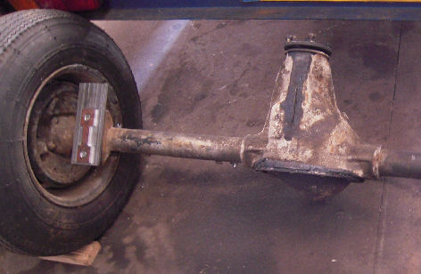
To attach the rear axle locators to the axle, I put some flat bar on my mill and fabricated these parts. Too bad only ants looking up will ever see them..... :-) |
|
|
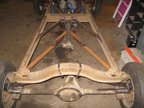
True to Henry's design, I made a complete wishbone to locate the rear axle. The wishbone is attached to the frame bracket by means of a Peugeot 307 bushing. |
|
|
|
These brackets will locate the front wishbone ball in the side- and vertical direction. I will design additional brackets for the fore/aft forces when these ones have been mounted in the frame. |
|
|
All brackets for the front wishbone mounted in the chassis. For additional strength the large holes in the centre crossmember have been filled with 3mm plates. While sitting next to the chassis, sipping my coffee, and admiring my work; I still could not agree with the somewhat crude transmission mount I fabricated earlier. It had to be simplified; and now is incorporated into the fore-aft brackets for the front wishbone. Also just visible in the picture of the new transmission mount is the bracket I made and fitted to house the brake and clutch master cylinders. |
|
|
|
Considering the car would probably get a chopped and channeled body, I lowered the floor to the lower flange of the frame rails. The pedals for brake and clutch have been designed in CAD by me. After trial fitting the shape with cardboard, I had them CNC cut from 10mm steel plate, and fitted them to the bracket holding the front wishbone. This is how it looked with the pedals and finished floor mounted in the frame. |
|
|
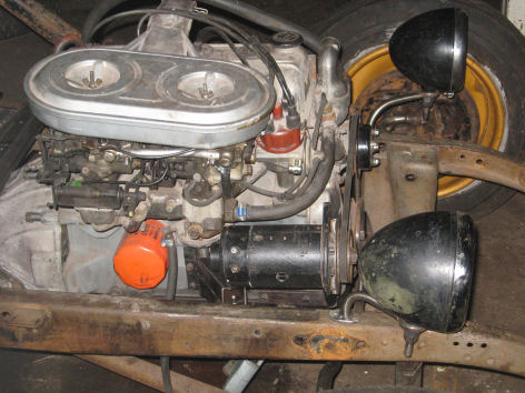
Other details needing attention were the electrics. On a Hot Rod a modern AC-dynamo would just not look right, so I opted for a vintage DC-unit formaly at home in an old Volvo. With the supply of electricity sorted, the battery needed a place too. To distribute the weight a little in the car, it was positioned on de passenger side of the car, just behind the central crossmember. I also managed to get my hands on a set of very cool, clear glass (!) Willocq Bottin headlights. To mount them close to the frame, I made some small brackets. |
|
|
|
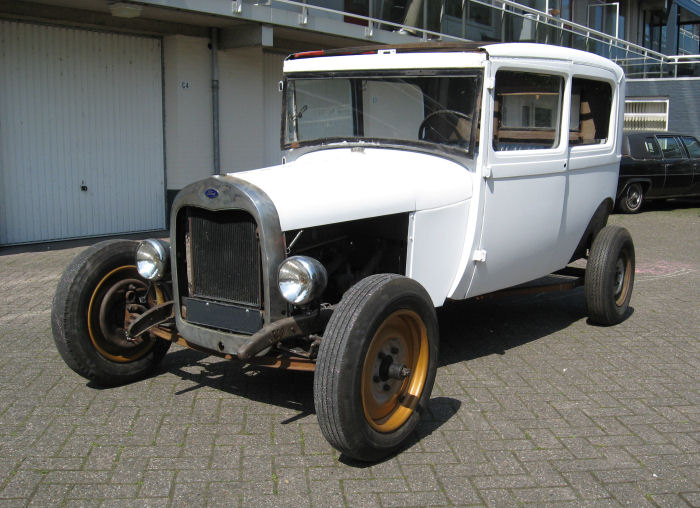
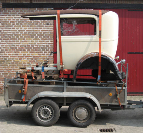
While making plans to go to Santa Pod to watch FIA and UEM Dragracing, and take a fibreglass roadster body back home, I got lucky. On the internet I found what appeared to be to good to be true: an original Ford Model A Tudor body! After getting her home, we put her on the frame, and mounted all the parts that came with it. This is how it looked when finished that night. The only major part missing, was the lower firewall. No big deal, because with the already planned channeling of the body, that part had to be modified anyway. |
|
|
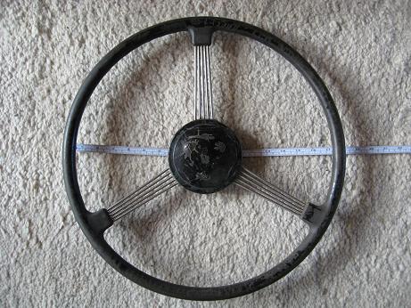
To make this steering wheel (of unknown origin) fit the Ford's column, these parts, tools and my lathe where used to come up with this adapter When installed in the car, it looked like this (sorry for the dark picture, it was quite late...). |
|
|
|
After bracing the body, and
cutting out everything that was preventing the body from dropping over the chassis, this is what the new look of my car was. After much measuring and tinkering with the body and chassis, brackets made of sturdy angle iron where fabricated, bolted to the chassis and welded to the body. |
|
|
Because of the channeling the angle of the steering column changed, so the original holes in the chassis for the steering box needed modification. By enlarging the hole for the sector shaft, and welding shut and redrilling one mounting hole, this was solved quite easily. I also made a new rod connecting the steering box to the left front wheel, and the rod connecting both wheels. Just a picture of the left front wheel with the new rods, and hydraulic brakes installed. |
|
|
|
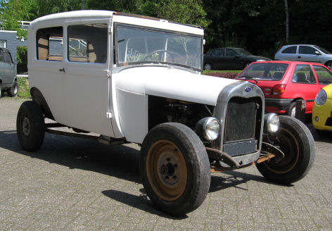
Just like with any project, a deadline was set; visit Scraper's Indoor Car Show 2009 (SINS 3) with the car! All kinds of small (?) jobs needed to be done: - install rear lights - make and install a 10 circuit wiring harness - make and install the lower firewall - make and install an accelerator pedal - make and install a floor for the rest of the interior - find and install something to sit on - sand and paint the body (white primer for now) - etc. The picture shown besides, is taken just prior to our departure to Belgium. Being it's maiden voyage, we unfortunately came to a stop after only some 5 km's, and did not make it.... Later investigation revealed it most likely was that we were low on gas, Bummer! |
|
|
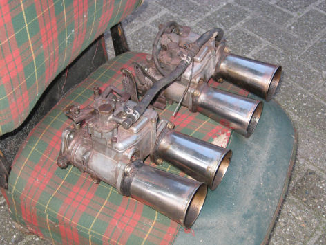
Later this winter I will see if I can get these side draft carbs to work on the engine. |
|
|